HISTORY
OF BRAKES AND LAWS
·
1925
MODEL T
·
1929
MODEL A
·
steel
rod going to each wheel, apply brakes manually
·
hydraulic
system, started with one master cylinder for all 4 wheels and
if
something broke, all braking was lost
·
1967
– New Law, must have a dual reservoir or tandem brakes
which would insure that there would be ½ the system if a hose broke.
FMVSS# - FEDERAL MOTOR VEHICLE
SAFETY STANDARD
·
“Brake
Bias” – because of
weight transfer, favoring one set of brakes over another
·
To
minimize rear wheel lockup
·
Problem
with just having front brakes
·
Past
bias was more like 60/40, now might be more like 80/20 or even 90/10 with the
shorter wheel base cars, These systems
are really like having two master cylinders, one part for half of the system
and one for the other half
·
Diagonal
split, 4 lines from master cylinder, if a rubber brake
hose broke, you would still have one front and one rear wheel braking which
gives even more controlled braking.
minimize rear wheel lockup lock up brakes in rear, you lose control
Diagonal
Base
brakes/Foundation brakes
–
Anti-Lock
Brakes –
Ways
to minimize rear wheel lock up? (to change to proper brake bias)
1. Size of calipers or cylinders
2. Size of Friction material
3. Hydraulic Valving
4. Brake design – disc/duo servo/non servo
(servo =less braking)
5. Size of the drum – bigger drum = more
leverage
Duo
Servo – has a wheel
adjuster (opposite of cylinder), will float a little; has cylinder and pivot at
top with star wheel at opposite side – servo action in forward or reverse
Non
Servo - a wheel adjuster next to cylinder, block at
bottom; cylinder and anchor block at opposite end – star wheel is next to
cylinder
Duo Servo
Servo – applies pressure to something else
Servo action - .030” clearance between drum and shoe,
force of one shoe pushes on the star wheel adjuster to the other shoe
Example: primary shoe – provides
some braking but also forces secondary shoe to brake
Self energizing – the rotation of the drum improves the
friction
Example: wedging action tries to
pull itself in making it more effective (pg.90)
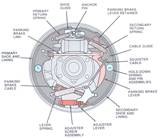 Move
out at top, away from anchor pin
Move
out at top, away from anchor pin
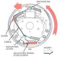
How
does self-adjuster work? When you are in
reverse and stop, why don’t they keep adjusting?
Non
Servo –Leading/Trailing
·
Less
efficient than duo server
·
Has
leading (front) – trailing (back)
·
Chances
are sizes are identical
·
Shoes
must come back to anchor pin – IF NOT,
SOMETHING IS WRONG!
·
Strut
rod on wrong, parking brake not releasing
·
This
can cause lock-up on that wheel, it gets a “head start” on braking
Hydro boost –Brake power assist that runs off power
steering pump
·
Hydraulic
lines from power steering to unit behind the master cylinder
|
Duo Servo |
I.D. |
|
Primary |
Secondary |
|
Edge brand: PRI |
SEC brand |
|
Smaller |
Larger |
|
Front of vehicle |
To rear of car |
|
Lighter in color |
Darker in color |
|
Less coefficient of
friction |
Higher COF |
If
you get these backwards; will still work, but will make a difference in inches.
Hubless Drum
1.
Centering cone on spring, aligning cup in lathe
2. Put hub on
3. Another aligning cup
4. Spacer – to equalize pressure
5. Nut/spacer combo
6. Machine tight together, less vibration
7. Push rod back in corner of hub
8. Put equalizer on top, turn knob in and out a little
9. Vibration dampener on hub
10. Step, stop lathe
Rough cut – 20 speed
·
Scratch
test, bit makes contact with drum - if
constant noise, OK
·
If
on/off noise – turn 1/2, moves in 1/2 inch
·
If 2
scratches are side by side – drum has high/low spot
- preferred scenario
·
If
in opposite sides – our mounting is wrong
Take
off at least .005” – each line is .002” = 2 1/2 lines
Herringbone
pattern – caused by not
installing vibration
Dampener – the leather belt
NOTE:
·
Don’t
machine if you don’t have a problem
·
Book
recommends only if at least a .015” - .020” groove
Machining
Drums
Cut
off as little as possible, but never less than .005”
A = depth of cut “5 to 20”
Start at B (on the closed
end) and move to C
Feed rate – how fast
you go from B to C
|
|
|
Depth |
Rate |
|
Optional
|
Rough
Cut |
.005” |
20
- .020” every rotation |
|
Required |
Finish
Cut |
.005” |
5 - .005”every revolution |
If
you cut too small an amount, the bit will float because it can’t dig in and
also because the chip of metal will be too small and will not dissipate
heat ______
A
brake lathe can be radius graduated or diameter graduated.
Radius
graduated – if turn dial
@ .004”, actually cutting .008” off of drum (double)
Diameter
graduated – if at .004
is .004, what you see is what you get
Amoco lathes are all
diameter graduated.
Some
rotors have a cooling groove.
LAB
DEMO – HUBBED ROTOR ON LATHE
1. Tapered adapter mounts inside - duplicates the plane of rotation
2. Equalizer
and 2 tapered adapters
3. Nut/spacer combo
4. Vibration dampener – [vented hub/lead
weights]
5. Uses cutting arm
6. Make sure you cut right up next to hat
7. Move knob in until you make contact
·
Adjust
sleeve to.0
·
Each
line is .002”
8. Spaces high/low high is for rough-cut,
towards machine _________________
9. Cut .005” off each side to take care of most
rotors (slow cut)
·
Minimum
is .003” off each side
[Can
rotate bits 3 times in each side, 6 rotations total]
10. After satisfied with cut, put a non
directional finish
·
A
Directional finish creates a noise – susceptible to frequency
·
Use
sandpaper, move back and forth as it turns
·
DA Sander/
lasts longer, tilt this way
·
Has
a plastic gear – “weak link”
11. When runs to end, there is a brass sleeve
will run off end of threads and won’t move anymore; it must jump back on, don’t
force
LAB
DEMO – Free Floating Axle
·
94
pre hubbed drum, drum has bearings
1. Take bolts off
2. Opposite side is lower, lube leaks to other
side
3. If nuts inside come loose, the dual wheels
can come out
4. Bolts – 1 for adjustment, 1 to lock up
It
is a good idea to replace seals anytime you do a brake job on a floating
rear axle.
·
If
it leaks, oil will get on brake shoes.
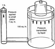
Pascal’s
Law
1. Cannot compress fluid
2. Fluid will take shop of the container
3. Pressure will be exerted in all directions
equally
[
Force
= P*A lbs.
Area = F/P
in2
Pressure
= F/A psi
 Strength vs
Speed
Strength vs
Speed
Force
= multiplier
Movements
= divides
·
Pump
brake pedal before you move it out of stall
·
Pads
must have contact with rotor
What
provides the small amount of clearance between pad and rotor:
1.
Rotor run out
2. Action of the square cut seal
Lower
brake pedal = Loose wheel bearings
Disc
Brakes:
1.
Self cleaning
2. Less Parts
3. Self adjusting
4. Run cooler
5. Less efficient, require more force
How
disc brakes are self adjusting?
·
The
master cylinder must be able to push piston out farther than the square cut
seal can move
What
can cause a low brake pedal?
·
Loose
wheel bearings
Input
– master cylinder
·
 Having
larger area at caliper makes it stronger, but a slower apply
Having
larger area at caliper makes it stronger, but a slower apply
How
much force at master cylinder?
·
Hydraulic
pressure is constant through whole thing
Area
of a Circle
.785 x (diameter)2
Must convert to square inches:
Example = 3” diameter piston
.785 x (3)2 =
7.065 in2
Curved piston = to get more surface area.