Steering and Suspension
S.A.I.
– Steering Axis Inclination
1.
Typical 5° - 8° on
2.
Typical 9° – 15° SAI on MacPherson
3.
Not a tire wearing angle
4.
Tilting of steering axis compared to true vertical
5.
Not adjustable – built into steering knuckle
6.
Provides for steering wheel returnability
Example: A car has maximum caster.
Added SAI,
so it has added returnability and no tire wear.
·
A tech notices caster is nonadjustable. Why is caster
Not as
important as it used to be? Because of added SAI
provides steering wheel returnability.
·
SAI lifts the car as you turn either direction.
MACPHERSON STRUTS
·
Replace bearings
·
Replace upper strut busing (possibly)
·
Usually just replace struts – reuse springs/coil
- Look for
oil
- Recommend
gas filled strut , helps ride feel
·
Put in spring compressor to loosen nut at top
- Mark when
you remove
·
May be able to buy cartridge to rebuild strut.
·
Tubing cutting – muffler tool – strut tool
·
Oil in, leave room for expansion
Terms: Alignment Equipment
Vernier caliper - specs
Tread depth gauge - video - guidelines
Flare nut wrench Valves as hydraulic brake system
Helicoil
Battery charging
Thread pitch gauge Composite, hubed, hubless rotor
Hand impact driver
Toe adjustment
LAB PRACTICAL
·
5 Minutes per station, 11 stations
·
Measure 3 drums
·
Measure rotors
·
Install drum on lathe – can you do it? Yes or no.
·
Vin – build date, assembly plant location, etc…find
info about vehicle
·
Drums set up – shoes which way on duo servo?
(Primary to
front; secondary to back; non servo, servo)
·
Identify steering arm and any steering linkage
TOE
·
A horizontal line through tire centerline
·
Last adjustment to be made
•Greatest
tire wearing angle
•The
distance between the front of the tires compared to the distance between the
rear of the
same tires.
•Parallel =
“0”
•Toe “in”
equals Positive
•Total Toe
(sum toe)
•Individual
Toe, compare toe of one tire to imaginary centerline of vehicle
•Toe can be
measured in DEGREES, or INCHES, or MILLIMETERS
•Measurement
in inches or millimeters consists of the difference between the front and the
rear of the tires
•When measured
in degrees, it is the difference between the vehicle centerline and the wheels
true plane of rotation or centerline.
• .125
(1/8th inch) off scuffs a tire 11 ft. sideways per mile (depends on tire
diameter)
Excessive
toe-in (positive) will scuff the outside of the tire
Excessive
toe-out (negative) will scuff the inside of the tire
The
sidewall flexes in the direction of the toe setting
NOTE Common wear with bias ply tires
indicate a saw tooth pattern
3 reasons for a straight steering wheel:
·
Psychological
·
Center to center travel of gear box
·
Proper turn signal cancellation
To straighten steering wheel, put on alignment
equipment, adjust tire rod ends, lengthen one, shorten other.
Turn signals – tabs built under steering wheel actually
cancel turn signals operation. If wheel
isn’t straight, premature or no cancellation will occur
The Ackerman Principle or Toe out on turns (TOOT)
is necessary because the inner wheels turn at a sharper radius than the outer
wheels
•
Provided by
angled steering arms
Adjust wheels evenly
to left or to right.
Low side turn – whichever side is lower, which
wheels are straight is the way the tires need to be turned.
TOOT – Toe Out On Turns
·
Front wheels toe out during turns
·
Inside wheel will turn sharper – this is to minimize
tire scrub during turns
·
Aka turning radius
·
2 Types
1. Symmetrical
2. Non-symmetrical
·
Because of offset engines
·
To minimize torque steer – pull during acceleration
·
Won’t see often
·
As you turn, the angle between the steering arm and inner
tie rod en becomes less, straightens out
·
Angled steering arm – What
physical part provides for TOOT? Angled steering arm.
Steering arm – connects to inner tie rod and part of
knuckle.
Springs – 3 types:
1. 1. Leaf Spring – bends, flexes
2. Coil – compresses
3. Torsion Bar
– twists
Torsion Bar – can be longitudinal or transverse
(side to side)
·
One advantage, it is adjustable by torquing down on the bolt, torques bar up more
·
Do not want to interchange from side-to-side
Leaf Spring – main leaf with eyelet
·
Shackle allows
leaf spring to change length or
Straighten
out during jounce and rebound
·
Multi-leaf – connected with center tie bolt, holds leaves together;
Locate
where rear end should be
Biggest reason tie bolt breaks is improper tightening of
U-bolts.
·
Avoid removing main leaf [Drawing]
·
When measuring, measure from hole
·
Don’t heat up – changes temper of steel
·
Tie bolts come longer, put nut on before you cut, but
on springs first
SPRING
·
Spring rate – how much force it takes to compress
spring ONE inch
·
2 Types::
1. Constant
rate – stays the same
2. Variable
rate – initial rate is low, but as it is compressed more, it becomes stiffer
Aka – cargo
coil
·
Convolutions or rings of a spring:
- If convolutions are same – constant
- If vary in distance – variable
·
To raise a car with leaf springs:
1. Extend
shackles
2. Add new
leafs – which will provide a rougher ride
·
Springs
1. New Springs
2. Spring
expanders – only but 2 in. within 45° of spindle
They are to
be mounted on 2 separate convolutions
CAMBER
•Tire
wearing angle
•Inward and
outward tilt of the tires
•Negative
when the top is tilted “in”
•0 degrees
when vertical
•Typical
ranges from 1/4 to 1/2 degree positive
Positive camber provides directional stability
•Projects
vehicle weight to inner wheel bearing, which decreases lever effect of the
spindle
Negative camber projects vehicle weight away from the inner wheel bearing
•This
decreases directional stability
•Results in
excessive road shock and a reduction in ride quality
CASTER
1.
Returnability
2.
Directional Stability
·
Normally specified positive, extensive because skinny
·
Frame angle
+ Frame
angle – higher in back
- Frame angle – higher in front
·
Manual – lower caster spec.
·
Power Steering – higher power steering
TURNING ANGLES
20deg. inside wheel and 18deg. Outside wheel
shows 1 1/2° difference
SAI – Returnability – directional
stability, enhanced road isolation
Spindle Arc –
SAI+ camber = included angle (IA)
front wheels be straight ahead prior to
measurement for accurate results
3 Alignment Types
·
Geometric centerline – obsolete
·
Thrustline – non adjustable rear suspension
·
Total 4 wheel alignment – adjustable rear suspension
NEGATIVE
Thrust Angle
Set-back - as close to 0 as possible on front wheel –
is farther back than other or forward
- right wheel to back –
positive setback ; will effect caster
RACK AND PINION
Never replace
with original equipment.
Rack - flat gear
Pinion – round gear
·
Has a torsion bar – only common link between steering
wheel and tires
- Built
into spool valve – rises need for assist
- Senses
how much resistance at tires during turning
·
In cold weather square cut seals may push to outside
– high pressure
- Will
start to wear soft aluminum inside housing
·
Can buy long or short – with or without tie rods,
etc.
·
Inner and outer tie rod ends
POWER STEERING
·
If you have problem with power steering, check belt
tension
·
Pump can put out 0-1400 psi, (All are approximate
pressures)
Idle = 100
psi
Highway
Driving while turning = 200 psi required
Parallel
Parking = 500-600 psi required
·
Power steering fluid has higher temp and pressure
rating than transmission fluid
Clockspring
·
Don’t wind up too tight
·
For airbag
·
So, don’t turn steering wheel when removing a rack
and pinion
Electrical Switch in Power Steering Circuit – pressure
switch, opens up circuit to AC air compressor at maximum pressure
Stabilizer Link –New style that can be damaged by
spinning with air tools:
Example
Intrepid, Toyota
·
Some are not interchangeable
·
Can make noise
Coil Springs and Stabilizer Bars
·
Smaller springs will have more body roll
·
The smaller coil springs, the bigger the stabilizer
bar
Sector Lash Adjustment (Gear Box)
3.
Sector shaft – changes rotary motion to reciprocating
motion
- Teeth on second gear are tapered
- Teeth mesh with recirculating ball
nut
·
Tapered – so when you
move shaft up, there is more clearance;
- Move shaft down, less clearance
- You want some clearance or lash,
only a small amount
·
Procedure: This
is subject to actual manufacturers service
procedures.
·
Straight ahead position (wheels), middle of gear box
is tightest point
·
Loosen lock nut and lightly bottom out shaft and back
it out half a turn
·
Lock it down, test drive to make sure that
there is no binding.
When removing Pitman Arm:
1.
Never hit on sector shaft, or use pickle fork
2.
Sector shaft is tapered
3.
Soft aluminum side cover supports sector
shaft – you could strip threads
4.
Why is a Pitman Arm puller so
short and stout?
It uses brute force twisting motion to separate; other pullers use the
force of the puller plus
hitting it to separate components.
Rack and Pinion Steering Never put any rotational twisting
force on a rack and pinion when removing a tie rod
Flex coupling – acts as a U-joint and to minimize vibrations from
pump to steering wheel.
3. Any
looseness is too much on a rack
4. Considered to
be a weak system – doesn’t have
angles to dissipate movement like a
parallelogram
linkage does and don’t forget inner tie rod
looseness.
·
What looseness we could get by with in the past on
SLA suspensions will cause vibration or shimmy on rack and pinion steering
systems.
RACK
AND PINION- backlash adjustment
5. Adjustment:
1.
Straight ahead position
2.
Loosen lock nut
3. Bottom out adjusting plug lightly- back out ½
turn
(still spring loaded with very little clearance)
If there were
any imperfection in the rack, turning could create a bind or tight spot.
This design
eliminates binding because spring can flex to prevent bind up.
·
In Ford, you take shims out to decrease back lash
Hidden Toe
Change
– toe change due to looseness in suspension while driving. This is caused by loose idler arms and other
looseness. Having two idler arms really
increases toe change.
Purging a Shock – getting air out
·
Expand a few times and compress before you put in a
car
·
Shock absorbers are used to control spring
oscillation and not to support the car.
·
When to replace?
1.
Oil leakage out of shock
2.
Time, lots of miles
3.
If it bounces more than it should (this is
hard to
tell)
·
Consider replacing with gas filled shocks
·
50/50 shock – as hard to pull out as it is to pull in
like used on a steering dampener.
70/30 shock ratio, 1st
number is extension and
second number is rebound. This is by engineering
information. Racetrack guys usually refer to this ratio
backwards from what engineers
do.
70
- Rebound – out or extension of shock.
/ 30
-jounce - in, compression of shock
At the track, a 90/10 shock on the front would allow the
front end to come up easily and go down slower.
Purpose
of SLA: Minimize tire scrub during jounce & rebound. This will allow the camber to change during
jounce and rebound but will minimize side-to-side scrub of the tire during this
movement. The normal or acceptable
camber change is called camber arc and is sometimes
around 1 ½ degrees during jounce and rebound.
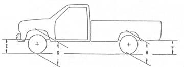
Importance of Proper Ride Height
Ride height measurement is really determining the angle of the suspension
components (like lower control arm position)
Whatever you do to one side of
car, it will try to do the opposite to the other.
- Because of weight transfer
-
Whether side-to-side or front/back
Usually when the driver sits
in the driver’s seat, the left camber will increase and the right camber will decrease.
·
If you do not have proper ride height, you will not be able to
minimize
the tire scrub during jounce and
rebound which is designed into the system at the factory.
·
Lowered or raised suspension will cause the tires to
wear more than they would with proper ride height. This changed condition puts the suspension
(control arms) at different angles and causes the ball joint to travel at
different locations of the arc which causes more side to side movement, thus
more tire wear.
·
Rolling radius –measuring from the middle of tire to
ground. This is used to insure that are
of the same size. This method takes into
consideration the flat spot on the bottom of the tire, which is hard to measure
otherwise.
Some
vehicles
·
Measure ride height – Some systems like the Chevrolet
truck will have the technician measure ride height and compensate with
different caster specs. This allows for
different frame angles because of different loads the truck in subjected
to. As and example, two identical trucks
might be used with different weight in them.
Best
way to Lower Vehicle – drop spindle, which is really a spindle raised
higher on the knuckle. This allows the
control arms to remain at proper angle while changing ride height.
Main purpose
of shock – control spring oscillations; it it does not hold up the
vehicle!
·
The spring of SLA must be stronger than McPherson,
Due to position of spring. The SLA spring is usually located ½ way out
to the ball joint so you could assume the spring needs to be about twice as
strong as the weight at that corner of the vehicle.
·
The smaller the coil spring, the larger the
stabilizer bar is what is usually recommended.
Scrub Radius – distance between 2 lines at the pavement. These two lines are the projected centerline
of the tire (camber) and the steering axis (same as included angle). If they
meet below the pavement, it is called positive scrub radius. If these two lines meet above the pavement,
it is called negative scrub radius. The
actual scrub radius is the distance between these two lines at the pavement.
Scrub Radius on SLA – typically have positive scrub
radius = lines intersect below the surface;
This
tends to toe out
Scrub Radius on McPherson Strut – negative scrub radius
·
Lines intersect above surface
·
Tends to toe in
·
Where the two lines intersect, either above the
pavement or below
·
Uses same 2 projected lines as included angle
·
As long as you have even braking, no problem
·
ABS – one pulses, steering wheel would turn, so they
decreased the scrub radius to minimize steering pull while in abs function. (As
it is pulsating brakes)
·
Deep dish, low profile
Offset wheels and low profile tires
will change the scrub radius
If Scrub radius changes because of different wheel
installed – can’t promise that it will
handle as it was designed.
SAI-
Steering Axis Inclination Typical
SLA - 5°- 8°
McPherson
Strut - 9°
- 15° or more
Is built into the steering knuckle and is not adjustable. Will aid in steering wheel return ability. I considered a non tire-wearing angle. SAI will tend to raise up each side while turning either direction. Increased SAI now does more to help return the steering wheel to straight ahead position so as not to depend on so much positive caster which is a cause of camber roll.